Technical Information
techquestions@techno-isel.com
21
Total Force = 100 lbs
(3)
Lead = 0.20 inches
Efficiency = 0.9 (Ball screw)
100 lbs × 0.20 inches
T = ––––––––––––––––––– = 3.54 lb-inches
2 (0.9)
Total Force = 25 lbs
(3)
Lead = 0.10 inches
Efficiency = 49%
25 lbs × 0.10 inches
T = ––––––––––––––––––– = 0.81 lb-inches
2 (.49)
The Torque required should be well below the torque rating of the motor chosen. A modest factor of safety should
be added to the torque required so that unexpected dynamic loads are safely handled by the driving system.
Selecting and Sizing Screw Drive Systems: When choosing a particular screw for a given application,
there are several factors to be considered. Required rpm, critical speed and maximum compressive strength
are the most important design features that determine screw design parameters, and can be calculated
according to the following equations. Since thread style design is irrelevant in these calculations, the same
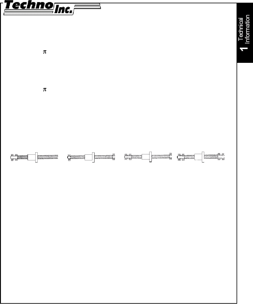
equations and charts can be used for both lead screws and ball screws. Bearing configuration must be
considered when using these equations. The following diagrams represent the typical bearing end support
arrangements.
linear velocity (in/min)
rpm = ––––––––––––––––––––
(4)
lead (in/rev)
The formulas above can be represented graphically by the charts on following pages. These charts have
been compiled for screws made of stainless steel. Speeds, loads, diameters, bearing arrangements and
products are referenced. It must be realized that a screw may be able to rotate at very high rpm’s, but the
nut may have more strict limitations. For this reason, we have truncated the ball screw rpm diagrams to a
top end of 4000 rpm, and provided each type screw with their own charts. Please note that the ball screw
charts are only represented for screws of 16 mm and 25 mm diameters.
A. Fixed-Free
B. Simple-Simple
C. Fixed-Simple
D. Fixed-Fixed
Maximum Speed:
d
CS = F (4.76 x 10⁶) –––
(5)
L2
where:
CS = critical speed (rpm)
d = root diameter of screw (inches)
L = length between supports (inches)
F = end support factor (see diagram)
case A.: 0.36
case B.: 1.00
case C.: 1.47
case D.: 2.23
Maximum Load
d4
P = F (14.03 x 10⁶) –––
(6)
L2
where:
P = maximum load (lbs) (critical load)
d = root diameter of screw (inches)
L = maximum distance between nut and load
carrying bearing
F = end support factor (see diagram)
case A.: 0.25
case B.: 1.00
case C.: 2.00
case D.: 4.00