20Phone: 516-328-3970www.technocnc.comTechnical Sectionlight being refl ected; but a basic rule of thumb for quality laser scanning is to have objects with uniform color and non
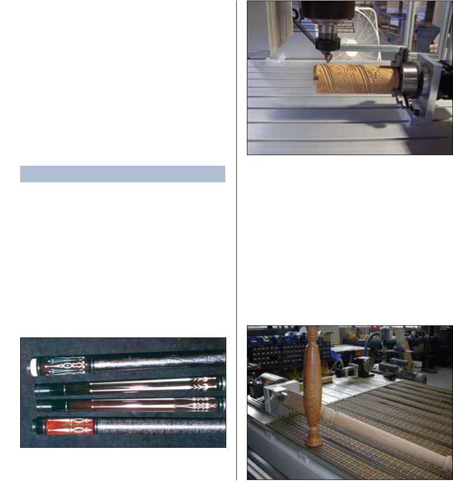
reflective surfaces. A common trick is to spray athlete’sfoot powder on the part to create a uniform surface.Also affecting the collection of points is the geometry of the object in relation to the location of the laser or touch probe. The XY-travel should not run parallel to any straight edges on the object. If a pass with the laser or touch probe is almost parallel to the edge, it will cross the edge at one or more points. Defining the edge with so few points will result in a jagged edge. To heed this caveat, skew the object before beginning the scan so that the laser’s XY-travel runs across any straight edges.The touch probe operates in similar fashion to the laser scanner, but is much simpler. It is not as detailed, accurate or fast, but it is the most affordable option.4th AxisSome CNC machines can be extended to utilize 4thaxis capabilities. Typically, a machine that cuts using a rotary table and tailstock uses a rotary axis as its 4th axis. Any machine with 4th axis capabilities greatly increases its potential work range for applications such as carving, scanning and indexing.Indexing is the simplest function to use on a 4th axis. Indexing is utilized for applications when multiple operationsare required on several different sides of a workpiece. In these cases, the axis is usually defined as the A-axis. Within a G-Code fi le, X-, Y- and Z-commands are provided for the machine’s three axes. At certain points in the fi le, rotary commands or “A” commands are given to index or rotate the part into a new position. A good example of indexing is inlay work performed on pool cues. The cue maker / programmer will program a pocket routine in the CAD/CAM software. He will then cut and paste the G-Code for the pocket several times with an A-axis command in-between each pocketing operation to rotate the part at regular intervals, typically 90°. Another type of 4thaxis application is sometimes called an axis swap. A toolpath for a flat part is generated with the intent of carving it on a cylindrical surface. This is done by swapping the X- or Y-axis for the rotary axis. Thus, the original X-axis of the fl at part is now going to be carved around the workpiece in the rotary table. This is the equivalent of wrapping the toolpath arounda part instead of along the X- or Y-axis.The last 4th axis application is what is referred to as true 4th axis machining. Toolpaths are generated using all 4-axis commands: X, Y, Z and A. This utilizes the full potential of the rotary table and allows the machine to create the part in the most effi cient and fl exible way. There are, in fact, several parts that cannot be made by swapping, but require true 4thaxis machining.