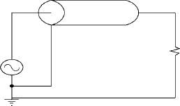
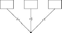
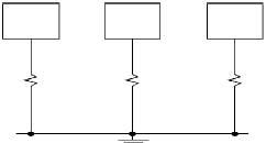
Techno Linear Motion Catalog40Technical InformationElectronic Noiseis a term used to describe unwanted disturbances as a result of electrical equipment.There are two sides to electric noise: the generation (or emission) of noise and the susceptibility of theequipment to noise.Susceptibilityto noise can be dealt with at the design level by taking several precautions. Encoders withTTL outputs should be avoided, and line driver encoders should be used. Similarly, differential input shouldbe used when possible rather than single-ended analog inputs. Finally, digital I/O should be electricallyisolated. One further precaution is to use an isolation AC power transformer, even if not required.Electrical Noise Generationcan be handled in a number of ways, and the following precautions should beobserved to minimize the possibility of system disturbance:- avoid creating ground loops in an electronic design- keep the low level logic wires (encoder wires) separated from the power wires (motorcables). If they need to cross each other, do so at 90 degrees to minimize the effectsof magnetic fields- use twisted pairs whenever possible- use shields when possible and necessary, and connect one end of any shield to ground- put surge suppression components on all electric coils (RC filters, diodes, MOV’s)- filter the power line using common RC filtersHaving taken these precautions, electric noise should be kept below the system disturbance level.Groundingof machinery is often done incorrectly. Some applications require that electrostatic dischargeon system hardware be kept to a minimum. The correct procedure is to connect a ground wire directly intothe ground at the back panel of the controller used. Any other grounding technique may produce a slightmismatch of ground potentials and subsequent noise problems.Motor Cable Gaugeselection should be made in accordance with standardized wire gauge selection tables.The gauge is determined based on power requirements. If a longer cable is preferred after selections havebeen made, it is recommended as a rule of thumb to move to a wire of heavier gauge, even if the desiredlength can handle the current. Quick calculations can be made as follows: Increasing a wire by 3 gaugesizes doubles the amount of copper in the wire and reduces the resistance by half. For example, goingfrom 22 gauge to 19 gauge doubles the amount of copper and halves the resistance.Use single point ground forfrequencies less than 1 MHzUse multipoint ground whenfrequencies are greater than1 MHz. Note that the groundleads must be kept short, oreven more noise could beintroduced into the system.The shield conductor shouldbe connected to the signalreference ground. It shouldbe connected at one pointonly.ShieldLoad