techquestions@techno-isel.com
69
33
13.5
18
8.6
40
4.5x7.5x5.3
7.7
10.2
0.058
0.058
0.16
33
8.5
18
8.6
40
4.5x7.5x5.3
7.7
10.2
0.058
0.058
0.16
37
15.5
22
11
50
4.5x7.5x5.3
8.2
12.8
0.08
0.08
0.22
37
8.5
22
11
50
4.5x7.5x5.3
8.2
12.8
0.08
0.08
0.22
42
19
24
15
60
4.5x7.5x5.3 16
22.7
0.19
0.19
0.42
42
10
24
15
60
4.5x7.5x5.3 16
22.7
0.19
0.19
0.42
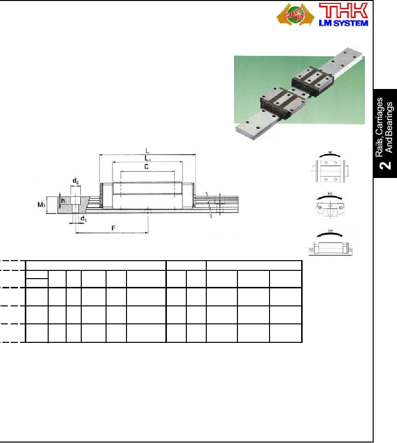
Type SHW with Caged BallTM Technology
Caged BallTM Technology is incorporated into an ultra-
wide highly rigid LM Guide type SHW. This product fea-
tures low noise levels, excellent high-speed operation
characteristics and long-term maintenance-free operation.
Its design conforms to that of the HRW type (same global
standard dimensions) and continues the HRW tradition of
wide rails and low center of gravity. This construction
makes SHW the ideal choice for locations where space is
very limited and high rigidity under the rolling moment (Mc)
is required.
LM Rail Dimensions
Basic Load Permissible Static Moment
WidthW2
W3Height Pitch d1xd2xh
C
C0
MA
MB
MC
W1
M1
F
kN
kN
kNm
kNm
kNm
Standard Lengths - mm
SHW17
SHW21
SHW27
160
230
280
480
480
640
1000
780
820
1900
1540
3000
Available Options:
1. Non-Standard Radial Clearances
2. Stainless Steel Carriages and Rails
(for SHW17 only)
3. Different Lubrication Types
4. Higher Accuracy Grades
For the Maximum Rail Lengths denoted by asterisks, the
distance from the end of the rail to the first mounting hole is:
* = 20 mm · ** = 25 mm · *** = 30 mm
Note: Standard distance from the end of
the rail to the first mounting hole is 15 mm.
***
**
*