| AIRFOIL DESIGNS HELP IMPROVE
SAILBOARD PERFORMANCE By Gerhard Opel
Analyst
Tectonics, Maui
Haiku, Hawaii
 A more efficient airfoil design combined with computerized
manufacturing technology is helping professional windsurfer racers improve their
performance. The author is a former aerospace engineer who applies optimized aerodynamic
profiles to the fins of windsurfing boards which are critical to their racing performance.
Accurate machining is critical to the success of this approach and
it was achieved by using an inexpensive CNC gantry machine that produces the fins to a
much higher level of precision than conventional manual methods. A more efficient airfoil design combined with computerized
manufacturing technology is helping professional windsurfer racers improve their
performance. The author is a former aerospace engineer who applies optimized aerodynamic
profiles to the fins of windsurfing boards which are critical to their racing performance.
Accurate machining is critical to the success of this approach and
it was achieved by using an inexpensive CNC gantry machine that produces the fins to a
much higher level of precision than conventional manual methods.
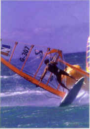
High performance windsurfing boards, which are generally
7'8" to 9'4" long, operate normally in a planing condition with only the rear
one-fourth to one-third of the board touching the water. This makes it impossible to use a
centerboard like that used in a sailboat to counteract the side force of the sail. The
only device providing counterforce is a small fixed fin at the rear of the board. The side
force provided by the fin stabilizes the board and balances most of the side force
generated by the sail under normal operating conditions. By allowing the use of larger
sails in higher winds, the amount of balancing side force generated by the fin controls
indirectly the level of attainable forward speed of the sail board. In
many cases, the performance of this fin is the most significant factor in determining the
overall performance of the board.
The fin operates in much the same manner as an airplane wing.
However, unlike the wing of a conventional airplane, the fin must work in both directions.
In this respect, it is similar to the function of wings used in certain fighter and
aerobatic airplanes that are designed to fly equally well upside down. While racing
windsurfing fins have traditionally been designed by trial and error, it occurred to the
author, who worked for 14 years as an aeronautical engineer, that optimized airfoil
designs which have been developed for aircraft could be transferred to sailboard fins with
little or no modification. Many of these designs were developed by the National Advisory
Committee for Aeronautics (NACA), the predecessor of the National Aeronautics and Space
Administration in the first half of this decade.
The problem in implementing this idea was how to produce
these airfoil designs to the required high level of accuracy. Fins for mass produced
windsurfing boards are produced from injection molded plastic. These fins are not used for
high-performance boards because the injection molded fins change their shape slightly as
they cool. These small changes can drastically reduce the performance of the board.
Fins for high performance boards are traditionally produced
by far more expensive manual methods. An experienced craftsman begins by building a series
of templates that describe the contours of the fin. The craftsman then uses these
templates as guides in producing the final form with a hand grinder. It typically takes
about a day to make a high performance fin. The accuracy of this approach leaves much to
be desired so it is necessary to test the fins in the water to determine whether or not
they are effective. A top name competitor will typically accept 2 out of 10 fins produced
by these methods.
 When the author originally developed the idea of building fins
according to optimized aerodynamic profiles, he assumed that it would be necessary to
build them using conventional manual techniques. While, as explained before, these methods
are quite expensive, an even greater problem in this case is their lack of precision.
Precision is much more important on fluid dynamic profiles because they are more sensitive
to minor dimensional inaccuracies which can cause the flow to separate from the fin,
suddenly reducing the side force and, in extreme cases, causing the board to suddenly
shoot sideways ("spinout"). When the author originally developed the idea of building fins
according to optimized aerodynamic profiles, he assumed that it would be necessary to
build them using conventional manual techniques. While, as explained before, these methods
are quite expensive, an even greater problem in this case is their lack of precision.
Precision is much more important on fluid dynamic profiles because they are more sensitive
to minor dimensional inaccuracies which can cause the flow to separate from the fin,
suddenly reducing the side force and, in extreme cases, causing the board to suddenly
shoot sideways ("spinout").
It was no secret that much greater accuracy could be achieved
with CNC machining but this alternative was not given serious consideration because it was
assumed that the machinery and software required to implement this technology would cost
at least $100,000. Unfortunately, the market for fins for high performance sailboards is
not large enough to justify this expenditure. Bernie Brandstetter, a
former Worldcup racer and the first manufacturer of CNC-milled sailboard fins on Maui,
introduced the author to the Techno-Isel machine.
Tectonics, Maui purchased a
3-axis CNC machine from Techno-Isel, New Hyde Park, New York, with the MAC100 controller
for only about $18,000. This system has an accuracy of +0.1 mm (+0.004) in
300 mm and a repeatability of +0.01 mm (+0.0004). Techno machines
have anti-backlash ball screws for play-free motion that make it possible to produce
circles that are accurate to the 0.0005 inch machine resolution. The ballscrews have
excellent power transmission due to the rolling ball contact between the nut and screws.
This type of contact also ensures low friction, low wear and long life. The ability to
achieve this accuracy at a low cost made economical fin machining possible.
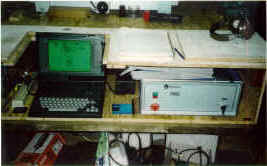 An aerodynamic reference book provides coordinates of the profile.
These coordinates are then entered into the Mastercam™ CNC (seen at left)programming
software package, developed by CNC Software, Inc., Tolland, Connecticut, and provided with
the Techno machine. The result is a plan view representation of the profile. The next step
is scaling the profile to create 30 to 40 ribs that give the fin's planform its third
dimension. The reference book provides the unit length of the profile used. The author
wrote a BASIC program that generates an array of points for each of the ribs scaled to the
cross sections of the fin's planform. The program produces its output in CadKey's™
CADLINK format which can be read by Mastercam. Mastercam reads these points as a series of
splines. A surface is then applied to these splines using Mastercam's lofted surface
feature. Another feature of the program, called synch, makes it possible to space the
chain intervals closely at 0.2 mm for the first 10% of the profile where accuracy is the
most important. Chaining intervals are spaced at 0.6 mm for the remainder of the curved
portion of the profile and at 2.4 mm for the flat portion in order to save time generating
the tool path and reduce the file size. An aerodynamic reference book provides coordinates of the profile.
These coordinates are then entered into the Mastercam™ CNC (seen at left)programming
software package, developed by CNC Software, Inc., Tolland, Connecticut, and provided with
the Techno machine. The result is a plan view representation of the profile. The next step
is scaling the profile to create 30 to 40 ribs that give the fin's planform its third
dimension. The reference book provides the unit length of the profile used. The author
wrote a BASIC program that generates an array of points for each of the ribs scaled to the
cross sections of the fin's planform. The program produces its output in CadKey's™
CADLINK format which can be read by Mastercam. Mastercam reads these points as a series of
splines. A surface is then applied to these splines using Mastercam's lofted surface
feature. Another feature of the program, called synch, makes it possible to space the
chain intervals closely at 0.2 mm for the first 10% of the profile where accuracy is the
most important. Chaining intervals are spaced at 0.6 mm for the remainder of the curved
portion of the profile and at 2.4 mm for the flat portion in order to save time generating
the tool path and reduce the file size.
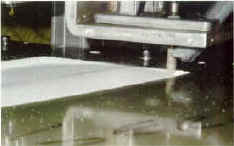
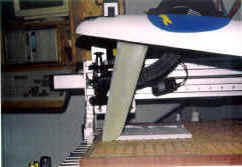
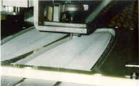 The milling machine makes it possible to produce fins to
precise aerodynamic profiles at a cost that is less than the cost of hand-producing high
performance fins. It takes about 4 hours to produce each fin. Feed rates are limited
because the G-10 plastic material used, the same type of material used to produce printed
circuit boards, is so tough. The material is supplied in half inch panels consisting of
about 25 layers of fiberglass embedded under pressure in a plastic shell. A carbide
bullnose endmill is used to cut this material. This tool is 3/8 inch in diameter, has 4
flutes, a 1/8 inch flat section around the centerline and 1/8 inch radius on each corner.
It makes a smoother surface than the more common ball nose end mill. The milling machine makes it possible to produce fins to
precise aerodynamic profiles at a cost that is less than the cost of hand-producing high
performance fins. It takes about 4 hours to produce each fin. Feed rates are limited
because the G-10 plastic material used, the same type of material used to produce printed
circuit boards, is so tough. The material is supplied in half inch panels consisting of
about 25 layers of fiberglass embedded under pressure in a plastic shell. A carbide
bullnose endmill is used to cut this material. This tool is 3/8 inch in diameter, has 4
flutes, a 1/8 inch flat section around the centerline and 1/8 inch radius on each corner.
It makes a smoother surface than the more common ball nose end mill.
The (NACA) 63A010 profile is one that has been found to
provide excellent performance under a wide range of racing conditions. The maximum
thickness of this profile is 35o back from the nose. Some modifications are required for
aerospace profiles because they are designed for considerably higher speed operation than
winsurfing fins. Tectonics, Maui uses a computational fluid dynamics program that
lets them simulate the operation of the profiles at the 30 to 40 mph speeds common to
sailboard racing. The gantry machine provides sufficient accuracy to make systematic
dimensional changes that allow performance to be optimized. The most critical
consideration is the prevention of the onset of turbulence, which causes a phenomenon
similar to stalling in an airplane. The fin than loses its side force and the sailboard
begins rapidly moving sideways. The accuracy of a computer milled fin makes it possible to
reduce the wetted area of the fin by 10%, reducing friction drag and increasing the
attainable speed of the board.
 Many races have been won with fins produced by computing milling
(right). Anders Bringdahl is only one of the well-known racers that have used the fins to
beat their best previous times. Other fin producers have tried to copy these profiles
using manual manufacturing methods and/or copymilling machines but found that performance
is substantially reduced by machining inaccuracies. The aerodynamic profiles have also
been used to produce molds, so far with mixed results due to uncontrollable shape changes
(see earlier in this article), used to produce mass-market sailboard fins. All in all,
computer milling technology is having a major impact on windsurfing by providing a better
performing fin at a reasonable cost for the performance achieved. Many races have been won with fins produced by computing milling
(right). Anders Bringdahl is only one of the well-known racers that have used the fins to
beat their best previous times. Other fin producers have tried to copy these profiles
using manual manufacturing methods and/or copymilling machines but found that performance
is substantially reduced by machining inaccuracies. The aerodynamic profiles have also
been used to produce molds, so far with mixed results due to uncontrollable shape changes
(see earlier in this article), used to produce mass-market sailboard fins. All in all,
computer milling technology is having a major impact on windsurfing by providing a better
performing fin at a reasonable cost for the performance achieved.
For more information, contact Techno, 2101 Jericho
Turnpike, New Hyde Park, NY 11040. Ph: 516-328-3970, Fax: 516-326-8827.
About the author: Gerhard Opel is a retired airline captain and a former bush pilot,
having flown in the Alaskan and Canadian arctic. He spent 14 years as an aeronautical
engineer working on various U.S. and European transport and fighter aircraft. He holds a
Graduate M.E. degree from the T.U., Vienna, Austria and a M.S.C. (ME) degree from the
Massachusetts Institute of Technology. He is also an enthusiastic board sailor learning a
lot from testing his own fin designs. He can be reached at 808-572-2294.
|